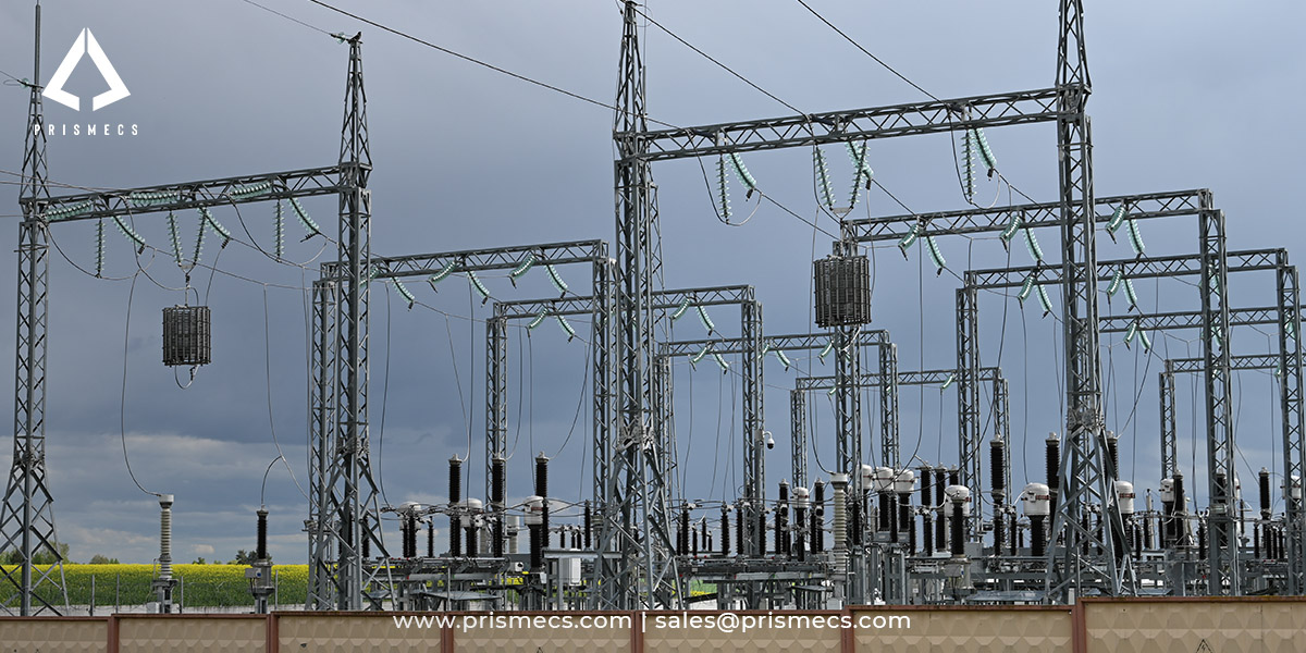
Substation protection is not a list of equipment. It is a set of numbered functions, applied to overlapping zones, coordinated so that the device nearest a fault operates first.
Fault currents routinely reach ten or more times normal operating current. Clearing them in the right place, in the right order, within milliseconds, is what stops a single fault from taking out a whole substation.
The components below deliver that. One of the most critical is a battery, and it appears on almost no list of substation protection equipment, including the one this page previously carried. Protective relays and breaker trip coils run on station DC. If the battery is flat, the fault does not clear.
This guide covers the functions, the zones, the twelve components, and what an owner should verify before energization.
What Substation Protection Actually Is
Protection detects abnormal conditions, isolates the smallest possible section of the network, and does it fast enough to limit damage to equipment and danger to people.
A fault is an unintended connection: phase to earth, phase to phase, or three phase. It creates a current path of very low impedance, which is why fault current is so much larger than load current.
Fault currents routinely reach ten or more times the currents used during regular operation. Equipment rated for normal load will be destroyed by fault current within seconds, and the energy released can injure or kill anyone nearby.
Protection has three jobs, in order of priority:
- Protect people. Clear the fault before the released energy reaches lethal levels.
- Protect equipment. Limit the duration of fault current through transformers, cables and switchgear.
- Protect the system. Isolate only the faulted section so the rest of the network keeps running.
That third objective is what makes protection a scheme rather than a collection of devices. Anything can trip everything. The skill is tripping only what is necessary.
For how substations sit within the wider transmission system, see our overview of electrical power transmission solutions.
ANSI Device Numbers: The Language of Protection
Protection functions are identified by numbers, not by equipment names, and those numbers are standardised in IEEE C37.2.
IEEE Std C37.2, Standard for Electrical Power System Device Function Numbers, Acronyms, and Contact Designations, defines base device numbers 1 to 99. The standard originated in 1928 and has been revised continuously; the current edition is IEEE Std C37.2-2022.
A single-line diagram does not say "overcurrent relay." It says 50/51. Learning the numbers is how an owner reads their own drawings.
The numbers that appear in most substations
50 and 51 are the pairing that does most of the work. Device 50 gives fast interruption for severe faults close to the relay. Device 51 gives the intentional delay that lets a downstream device clear a distant fault first. They are commonly specified together as 50/51.
Device 87 is the sharpest tool. Because it compares current in against current out, it responds only to faults inside its protected zone, which means it can operate instantly without any coordination delay.
The suffix trap
IEEE C37.2 defines the base numbers and does not standardise suffix letter usage. That has a practical consequence most references omit.
Breaker failure protection is not a standard C37.2 device number. The designation 50BF is primarily a GE Multilin convention; other manufacturers use 52BF or proprietary codes. Devices 95 to 99 are the user-defined range for functions the standard does not cover.
Suffixes that are widely used and worth knowing: 87T for transformer differential, 87B for bus differential, 87G for generator differential. 50G, 50N and 50P for ground, neutral and phase instantaneous overcurrent, with 51G, 51N and 51P the time-delayed equivalents.
Specify the function, not just the code. A specification saying "50BF" to a supplier using a different convention invites a quotation for something else.
One relay, many functions
Modern microprocessor relays perform many protective functions in a single device. The standard designates a multifunction device as 11, and device numbers are still shown on single-line diagrams and schematics to indicate which specific functions are enabled.
That matters commercially. A multifunction relay is not protection until the functions are configured, set and tested. The hardware is a fraction of the delivery.
ANSI and IEC
IEC 60617 provides different symbols and terminology for most of the device numbers defined by C37.2. On a project mixing North American and European equipment, both conventions will appear on drawings, and the specification should state which governs.
Zones of Protection
A zone of protection is a defined section of the network with its own protective devices, and zones deliberately overlap so that no point is left unprotected.
Typical zones in a substation: the incoming line, the bus, the transformer, and each outgoing feeder. Each is bounded by circuit breakers and monitored by its own relays.
Zones overlap at the circuit breakers. A fault in the overlap trips both zones, which means slightly more of the network goes out than strictly necessary. That is the deliberate trade: overlap costs a little selectivity and guarantees there is no blind spot.
Primary and backup protection
Primary protection is the scheme intended to clear a fault in its zone, as fast as possible. Backup protection operates if the primary scheme fails.
In transmission line protection, instantaneous overcurrent (50) and time overcurrent (51) relays are often configured as backup to distance relays (21), so that if the primary distance protection fails to clear a close-in fault, the overcurrent elements provide delayed tripping while maintaining selectivity across zones.
Breaker failure protection
A relay can operate correctly and the breaker can still fail to open. Breaker failure protection detects that.
It starts a timer when a trip is issued and checks whether current has actually stopped flowing. If the breaker fails to clear within the programmed delay, typically 100 to 500 milliseconds, the scheme sends backtrip commands to the upstream breakers.
Without it, a stuck breaker means a fault that never clears. The upstream device eventually operates on its backup setting, far more slowly and taking out far more of the network.
If the breaker fails to trip
This is why breaker failure protection exists and why breaker trip testing belongs in the maintenance programme. A breaker that has not been operated in years may not operate when it is needed, and the only way to know is to test it.
Coordination and Selectivity
Selectivity means the protective device closest to the fault operates first, and coordination is the time grading that achieves it.
A coordination study determines time-current characteristic (TCC) settings for selective fault clearing. It plots every device's operating curve on the same axes and confirms that downstream devices operate before upstream ones across the full range of expected fault currents.
Device 51 operates with an intentional delay inversely proportional to current magnitude, which is what allows downstream devices to clear faults first. The delay is not a limitation; it is the mechanism.
If coordination is wrong
Two failure modes, both expensive.
- Too slow downstream, and the upstream device operates first. A feeder fault takes out the whole bus, and the outage is far larger than the fault warranted.
- Too fast upstream, and selectivity is lost entirely. Every fault anywhere trips the main breaker.
A coordination study is not a one-time deliverable. It must be revisited when the source impedance changes, when generation is added, when a transformer is replaced, or when load grows enough to move settings. A study performed at commissioning and never revisited describes a network that no longer exists.
The Four Types of Substation
Four substation classifications exist, and their protection requirements differ substantially by voltage class and fault current exposure.
- A transmission substation steps up voltage from a generating station for long-distance transfer, using a large power transformer. Highest voltage class, highest fault duty, and the most complex protection.
- A distribution substation steps voltage down for local delivery, taking two or more transmission or sub-transmission lines as input. Many outgoing feeders, each with its own protection.
- A converter substation converts between alternating and direct current, serving HVDC links and traction supplies. It changes current type, not frequency. Frequency conversion is a separate function used in some traction systems.
- A switching substation routes power between circuits without transforming voltage. No transformer, so no transformer protection, and the scheme centres on bus and line protection.
Each type occupies a distinct position in the power delivery chain, and protection configurations differ by voltage class, fault current exposure and grid interconnection requirements.
The Twelve Components
Twelve components make up a substation's protection and switching equipment, organised by what they actually do.
Detection and measurement
1. Current transformers (CT). Sample high primary currents and scale them to standardised low-level outputs for relays and metering.
2. Voltage transformers (VT), also called potential transformers. Sample high system voltage and deliver low voltage to relays and meters, so instrumentation is never exposed to the primary circuit.
3. Protective relays. The intelligence layer. They receive CT and VT signals, compare them against settings, and issue trip commands.
Interruption and isolation
4. Circuit breakers. Automatically interrupt fault current on a relay command. Fault currents may be ten or more times normal operating current, and the breaker must interrupt them without damage.
The common types: vacuum circuit breakers, widely used at medium voltage; SF6 circuit breakers, dominant at transmission voltage; and air circuit breakers, common at lower voltages and in older installations.
Key ratings to specify: rated voltage, rated continuous current, short-circuit breaking capacity, and interrupting time, typically expressed in cycles.
5. Isolators, also called disconnect switches. Manually operated mechanical switches that isolate a section for safe working, and they provide the visible break that makes an isolation verifiable.
An isolator must not be operated under load. It has no arc-interrupting capability. Opening one on load produces a sustained arc, which is why isolators are mechanically or electrically interlocked with the associated circuit breaker.
6. Lockout relays (device 86). Trip and latch, preventing reclosure until the cause has been investigated and the relay manually reset.
Surge and insulation
7. Surge arresters, also called lightning arresters. Connected between line and earth close to the equipment, they divert surge energy to ground during lightning strikes and switching transients.
Key ratings: maximum continuous operating voltage (MCOV) and energy class. An arrester with insufficient MCOV conducts under normal system voltage; one with too high an MCOV does not protect.
8. Insulators. Restrict the movement of electric charge, providing high resistance and preventing short circuits. Types include suspension, strain, shackle and pin, selected by mechanical loading and voltage class.
Basic insulation level (BIL) is the specification parameter, defining the impulse voltage the insulation must withstand.
Conduction and structure
9. Bus bars. Conductors linking equipment where heavy currents flow, typically bare copper or aluminium, rectangular or tubular in section.
Outdoor bus bars come in two forms: rigid and strain. Rigid tubular bus maintains fixed clearances that never change, which simplifies clearance compliance. Strain bus uses tensioned conductors between structures.
10. Conductors and terminations. Connect equipment within the yard and to incoming and outgoing circuits.
Earthing and DC
11. Earthing and ground grid. Provides the fault current return path and keeps touch and step voltages within safe limits.
12. The DC system: station battery, charger and DC distribution. The component almost no list includes, covered in full below.
Lead times
Power transformers, breakers and large conductor currently carry lead times of 90 to 130 weeks, roughly two to two and a half years. For the demand conditions driving that, see our analysis of power generation trends and equipment availability.
Instrument Transformers: The Specification That Decides Protection Performance
A current transformer samples high primary current and scales it to a standardised low-level output, typically five amps or one amp, suitable for feeding protective relays and metering without exposing instrumentation to the primary circuit.
CT accuracy class and burden rating are the critical selection parameters, because errors in current measurement directly compromise the sensitivity and selectivity of differential protection, overcurrent relays and revenue metering.
The four parameters
- Ratio. Primary to secondary, for example 600:5. It must match both the expected load current and the fault current the relay needs to see.
- Accuracy class. Protection CTs and metering CTs have different accuracy requirements. Metering accuracy matters at normal load; protection accuracy matters at fault current. A CT specified for one is frequently wrong for the other, which is why many installations use separate cores.
- Burden. The total impedance of everything connected to the CT secondary: relays, meters, and the wiring itself. Exceeding the rated burden causes the CT to saturate.
- Knee point voltage. The point beyond which the CT no longer reproduces primary current faithfully.
What happens when a CT saturates
The secondary output no longer represents the primary current. A saturated CT under fault conditions can under-report the fault, so the relay sees less current than is actually flowing and operates slowly or not at all.
This is the most consequential failure mode in the measurement chain and it originates in a specification error, not a component failure. Burden calculations should be performed for the installed configuration including cable runs, not assumed from the relay datasheet.
Voltage transformers are specified similarly, on ratio, accuracy class and burden. Their failure mode is different: a lost VT signal can cause undervoltage elements to operate incorrectly, which is why VT supervision is a standard relay function.
The DC System: The Component Nobody Lists
Protective relays and circuit breaker trip coils run on station DC. If the battery system fails, relays may still detect a fault and no breaker will open.
The DC system is protection equipment. It belongs on any list of substation protection components and it is absent from almost all of them, including the version of this article that preceded this one.
It comprises three parts: the station battery, usually lead acid or nickel cadmium; the battery charger, which maintains float charge and supplies steady-state DC load; and DC distribution, the panel and circuits feeding relays, trip coils, control and indication.
The failure mode
The charger fails, which is often silent. The battery carries the load until it discharges. Nothing appears wrong until a fault occurs and the breaker does not trip.
By then the protection scheme, the coordination study and every relay setting have been rendered irrelevant by a component costing a small fraction of the substation.
What to test and how often
Capacity testing to confirm the battery still delivers its rated duty cycle, since capacity degrades with age and a battery at 70 percent capacity may not sustain a trip after an extended outage. Charger output monitoring and alarming, because charger failure must raise an alarm rather than wait to be discovered. Cell voltage and impedance checks to identify weak cells before they fail. DC earth fault monitoring, since a single earth fault on the DC system is tolerable and a second can cause spurious tripping or prevent tripping entirely.
IEEE has a standards series covering stationary battery sizing, installation, maintenance and testing, and battery maintenance is a defined O&M scope item rather than an inspection afterthought.
For how this fits a wider maintenance programme and its reliability metrics, see our guide to power plant O&M metrics and contracts.
Grounding: IEEE Std 80
Substation grounding is designed to a standard, and the calculation that governs it is about human survival rather than equipment protection.
IEEE Std 80, Guide for Safety in AC Substation Grounding, is the governing reference. It sets out the design of the ground grid and the calculation of safe voltage limits.
Step and touch potential
When fault current flows into the earth, it creates a voltage gradient across the ground surface.
Step potential is the voltage difference between a person's two feet, roughly one metre apart, standing on that gradient. Touch potential is the voltage difference between a person's hand touching a grounded structure and their feet on the ground.
IEEE Std 80 calculates the tolerable limits based on fault current magnitude, clearing time, soil resistivity and body weight assumptions, then the grid is designed so that actual step and touch voltages stay below them.
Clearing time is a direct input. Faster protection means higher tolerable voltages, which means a less expensive ground grid. Protection design and grounding design are coupled, and treating them as separate work packages produces either an overdesigned grid or an unsafe one.
What the ground grid does
Conductors buried in a grid pattern across the yard, bonded to every structure, equipment enclosure and fence. It provides the fault return path, equalises surface potential, and limits the voltage rise of the grid relative to remote earth.
If the grid is inadequate
Soil resistivity testing before design, and grid resistance measurement after installation, are the two verification points. A grid designed on assumed soil resistivity and never measured is an assumption carrying a safety consequence.
Arc Flash and Personnel Safety
Arc flash is the dominant personnel hazard in substation work, and the protection required is determined by calculation rather than by rule of thumb.
Substation personnel working in high-voltage environments require arc-flash rated clothing, insulated rubber gloves with leather protectors, voltage-rated safety boots, arc-rated face shields, and hard hats rated for electrical hazard exposure as the minimum PPE baseline.
Arc-flash protection requirements are determined by incident energy analysis specific to each substation's fault current levels and protective device clearing times, which means PPE specifications vary significantly between distribution-level and transmission-level facilities.
NFPA 70E, Standard for Electrical Safety in the Workplace, governs the analysis, the labelling and the work practices.
Protection settings change the hazard
Incident energy is a function of fault current and clearing time. A protection setting that clears faster reduces the energy released, which reduces the PPE category required to work on that equipment.
That is the mechanism behind three practices the industry uses during live work:
- Quick-trip settings, temporarily reducing relay time delays during maintenance so that any fault clears faster and incident energy falls.
- Arc-flash protection systems, using light and current detection to trip in a few milliseconds.
- Breaker reclose disablement, preventing automatic reclosure onto a fault while people are working, because a reclose into a fault re-energises the hazard with personnel present.
These are settings changes, which means they are protection engineering decisions with a safety consequence, and they must be reverted and verified afterwards.
Labelling and training
Equipment must carry arc flash labels stating incident energy and required PPE category, derived from the study. Those labels are only as current as the study behind them, and a study that predates a source impedance change is wrong.
Substation Automation
Modern substations communicate protection and control data over a network standard rather than through hardwired connections.
IEC 61850 is the international standard for communication networks and systems in substations. It defines data models, device naming and communication services, and it is what allows relays from different manufacturers to exchange information.
GOOSE messaging, Generic Object Oriented Substation Event, allows relays to exchange trip and interlock signals over the network in milliseconds, replacing hardwired trip circuits between devices.
The commercial consequence: interoperability is a specification issue, not a given. IEC 61850 conformance certificates and tested interoperability between the specific devices proposed should be required at tender, because conformance to the standard does not guarantee two devices will work together.
For how these communication standards extend to distributed energy interconnection, see our guide to smart grid and distributed energy resources.
Supporting Equipment
Three items appear in every substation, belong in the equipment list, and are not protection.
Capacitor banks provide reactive power compensation, correcting power factor and reducing the phase difference between voltage and current. They improve system efficiency and voltage regulation. They do not detect or clear faults, and they require their own protection rather than providing it.
Fencing prevents access by unauthorised persons and livestock. Fencing height should typically be at least 1.8 metres, and the fence must be independently earthed and bonded to the ground grid, because an ungrounded fence near a substation can rise to dangerous potential during a fault.
Distribution panel boards in the control room distribute low-voltage AC supplies for lighting, heating and auxiliary equipment. The earthing conductor bonds the panel frame to the earth grid, and an insulating mat of appropriate rating is placed in front of the panel.
Naming these as protection equipment, as many lists do, obscures what protection actually is. They are substation equipment. That is a different category.
What to Verify Before Energisation
Protection is delivered as settings and test records, not as hardware, and an owner who accepts the hardware without the documentation has accepted an unverified scheme.
The five deliverables
The coordination study, showing time-current curves for every device across the expected fault current range, with the source impedance and system configuration it assumed.
Relay setting files, in native format, with a printed settings report. These are the scheme. A substation with relays and no settings files cannot be modified, extended or troubleshot without re-engineering.
Primary injection test records, proving the complete chain from CT through relay to breaker trip coil actually operates. Secondary injection tests the relay; primary injection tests the scheme.
Breaker trip and timing test records, confirming interrupting time against specification.
Battery capacity test and charger commissioning records.
Ownership
Establish that you own the relay setting files, the coordination study and the configuration, in native format, with no restriction on engaging a different contractor.
This is the same trap as the SCADA configuration clause and the CMMS data clause. A contractor holding your settings files controls every future modification, because nobody else can safely change a scheme they cannot read.
Insurance and compliance
Insurers assess protection adequacy and maintenance records when pricing industrial electrical risk. Where the substation forms part of the bulk electric system, NERC reliability standards impose protection system maintenance and testing obligations with defined intervals and documentation requirements.
If settings files are lost
The practical remedy is re-engineering: a new coordination study, new settings, and full retesting. It costs a multiple of what retaining the files would have, and it is a routine consequence of not writing the ownership clause.
Governing Standards
Seven standards frames govern substation protection design, equipment and safety.
Outside the United States
IEEE and ANSI conventions dominate North America. IEC standards, including IEC 60617 symbols and terminology, dominate most other markets. On international projects both appear, and the specification must state which governs where they differ.
National grid codes add further requirements on fault ride-through, protection settings and disturbance recording, and they are not interchangeable between jurisdictions.
How Requirements Vary by Application
The standards are constant. What changes is the fault duty, the redundancy expectation and who sets the rules.
Utility transmission. Highest voltage and fault current, full redundancy with duplicated protection systems on separate DC supplies, and mandatory compliance and reporting where the asset is part of the bulk electric system.
Utility distribution. Many feeders, auto-reclosing to clear transient faults, and coordination with downstream fuses and reclosers.
Industrial substations. Protection coordinated with the plant's own distribution, and the process rather than the grid defines the cost of an outage. Motor protection and arc flash mitigation carry more weight than on a utility site.
Data centres. Selectivity is the dominant requirement, because a fault that trips more than the affected circuit breaches the redundancy design. For what those redundancy levels require, see our guide to data centre power redundancy.
Generation interconnection. Protection must satisfy the grid operator as well as the owner, including synchronising, anti-islanding and disturbance recording. Settings are frequently specified by the utility rather than chosen by the owner.
Oil and gas and hazardous areas. Equipment must satisfy area classification requirements alongside protection function, which constrains equipment selection before protection philosophy is considered.
Renewable interconnection. Inverter-based sources contribute much lower fault current than synchronous machines, which can leave conventional overcurrent protection unable to detect a fault at all. For technology selection context, see our guide to power generation equipment compared.
What Prismecs Does
Prismecs delivers, installs and commissions power generation plant including its electrical interconnection, and supplies equipment for power and industrial infrastructure.
The most directly relevant delivered scope is Birr, Switzerland, where eight TM2500 dual-fuel units totalling 260 MW were built as a fast-track reserve plant, online in six months, with a new 220 kV interconnection on a compact site.
Other delivered project scope includes four TM2500 units totalling 110 MW at Duqm, Oman, kept grid-ready with resident O&M crews, CMMS and parts support; an LM2500XPRESS plant at Miaoli, Taiwan delivered in ten months; three LM6000PC units adding 150 MW of fast-start reserve; and an LM6000 fleet decommissioned in Norway, transported and recommissioned at a new site.
Capability spans I&C services for instrumentation, controls and electrical systems, EPCM services for project delivery, O&M services for the operating phase, ready-to-ship equipment inventory including transformers and generators, owner's engineering for independent review, and technology and consulting. Sector context is on the power utilities page.
Apply this article's criteria to any contractor, including us. Ask who produces the coordination study and who owns the settings files afterwards. Ask whether primary injection testing is in scope or only secondary. Ask how the battery system will be capacity tested at commissioning. Ask which convention governs where ANSI and IEC designations differ.
To discuss substation equipment or an electrical scope, send your voltage class, fault level, single-line diagram and the outcome you need to sales@prismecs.com or call +1 (888) 774-7632.
Frequently Asked Questions
What is substation protection equipment?
The equipment that detects electrical faults, isolates the affected section and limits damage to plant and danger to personnel. It comprises current and voltage transformers for measurement, protective relays for detection and decision, circuit breakers for interruption, isolators for safe isolation, surge arresters, insulators, bus bars, earthing, and the station DC system that powers the relays and trip coils. Fault currents routinely reach ten or more times normal operating current.
What are ANSI device numbers?
Standardised numbers identifying protective functions, defined in IEEE Std C37.2, Standard for Electrical Power System Device Function Numbers, Acronyms, and Contact Designations. The standard originated in 1928 and defines base numbers 1 to 99, with the current edition being IEEE Std C37.2-2022. Single-line diagrams show functions by number rather than name, so 50/51 means combined instantaneous and time overcurrent protection.
What is the difference between device 50 and device 51?
Device 50 is instantaneous overcurrent with no intentional time delay and a trip time under 50 milliseconds, providing fast interruption of severe faults. Device 51 is AC time overcurrent with an inverse-time characteristic, tripping faster as current rises, and its intentional delay is what allows downstream devices to clear distant faults first. They are commonly specified together as 50/51.
What is device 87 differential protection?
Device 87 compares the current entering a protected item of equipment against the current leaving it. In healthy operation the two match. If they do not, the fault is inside the protected zone and the relay trips instantly. Because it responds only to internal faults, it needs no coordination delay. Suffixes indicate application: 87T for transformer, 87B for bus, 87G for generator differential.
Is 50BF a standard ANSI device number?
No. IEEE C37.2 defines base device numbers 1 to 99 but does not standardise suffix letter usage, and breaker failure is not a standard C37.2 number. The designation 50BF is primarily a GE Multilin convention; other manufacturers use 52BF or proprietary codes, and devices 95 to 99 are the user-defined range. Specify the function rather than relying on a code convention that varies by supplier.
What is a zone of protection?
A defined section of the network with its own protective devices, typically the incoming line, the bus, the transformer and each outgoing feeder. Zones deliberately overlap at the circuit breakers so that no point in the substation is unprotected. A fault in the overlap trips both zones, taking out slightly more than strictly necessary, which is the accepted trade for having no blind spot.
What is protection coordination and selectivity?
Selectivity means the protective device closest to a fault operates first, isolating the smallest possible section. Coordination is the time grading that achieves it, established by a coordination study that plots time-current characteristic curves for every device across the expected fault current range. Device 51's intentional delay, inversely proportional to current magnitude, is the mechanism that lets downstream devices clear first.
What is breaker failure protection?
A scheme that detects when a circuit breaker fails to open after receiving a trip command. It starts a timer on trip and checks whether current has stopped flowing. If the breaker has not cleared within the programmed delay, typically 100 to 500 milliseconds, the scheme sends backtrip commands to upstream breakers. Without it, a stuck breaker leaves a fault clearing only on slow upstream backup settings.
Why does CT accuracy class and burden matter?
Because errors in current measurement directly compromise the sensitivity and selectivity of differential protection, overcurrent relays and revenue metering. Burden is the total impedance of everything connected to the CT secondary, including wiring. Exceeding rated burden causes saturation, and a saturated CT under fault conditions under-reports the current, so the relay operates slowly or not at all. Calculate burden for the installed configuration.
Why is the station battery protection equipment?
Because protective relays and circuit breaker trip coils run on station DC. If the battery system fails, a relay can correctly detect a fault and no breaker will open. The failure is usually silent: the charger fails, the battery carries the load until it discharges, and nothing appears wrong until a fault occurs. Capacity testing and charger alarming are the controls.
What is IEEE Std 80 and why does clearing time matter?
IEEE Std 80, Guide for Safety in AC Substation Grounding, governs ground grid design and the calculation of tolerable step and touch potential. Step potential is the voltage between a person's feet on the ground gradient during a fault; touch potential is between hand and feet. Clearing time is a direct input, so faster protection raises tolerable voltages and reduces ground grid cost.
What PPE is required for substation work?
Arc-flash rated clothing, insulated rubber gloves with leather protectors, voltage-rated safety boots, arc-rated face shields and hard hats rated for electrical hazard exposure, as the minimum baseline. Requirements are determined by incident energy analysis specific to each substation's fault current levels and protective device clearing times under NFPA 70E, which means specifications vary significantly between distribution-level and transmission-level facilities.
What are the four types of substation?
Transmission substations step up voltage from generating plants for long-distance transfer. Distribution substations step it down for local delivery. Converter substations manage AC to DC conversion for HVDC links and traction systems, changing current type rather than frequency. Switching substations route power between circuits without voltage transformation. Protection configurations differ substantially by voltage class, fault current exposure and interconnection requirements.
Why must an isolator never be opened under load?
Because it has no arc-interrupting capability. An isolator is a mechanical switch providing a visible break for safe isolation, not a fault-clearing device. Opening one while current flows produces a sustained arc that can damage equipment and injure personnel. Isolators are mechanically or electrically interlocked with the associated circuit breaker so the breaker opens first and the isolator only operates on a dead circuit.
Who should own the relay setting files?
You should, explicitly and in writing. Require the coordination study, the relay setting files in native format, primary injection test records, breaker timing records and battery capacity test records, with no restriction on engaging a different contractor. A contractor holding your settings controls every future modification, because no one else can safely change a scheme they cannot read. Recovery means full re-engineering and retesting.
Tags: Substation Protection ANSI Device Numbers Protective Relays Circuit Breakers Substation Grounding
recent posts
Power Utilities
16 minutes read
What Is a Mobile Gas Turbine Power Plant? TM2500-Class Units Explained
A mobile gas turbine power plant is a transportable power generation system designed to add electrical capacity faster than a conventional permanent p...

Power Utilities
20 minutes read
Fast-Track Power Plants Deployment: How to Reach Speed to Power in Under 12 Months
Fast-track power plant deployment can hit first power in weeks. See real TM2500 timelines from permitting to COD, proven in Oman and Taiwan. Plan your...

O&M Services
11 minutes read
Gas Turbine Outage Planning: Schedule, Scope Rules, and Checklist
Gas turbine outage planning starts 18 months out. Get the T-minus schedule, scope freeze rules, parts readiness gates and checklist. Talk to a Prismec...

O&M Services
15 minutes read
Predictive vs Preventive Maintenance: How to Choose Per Asset
Most plants apply predictive vs preventive maintenance facility wide and overspend. Match each asset by failure mode, criticality and P-F interval. Ta...