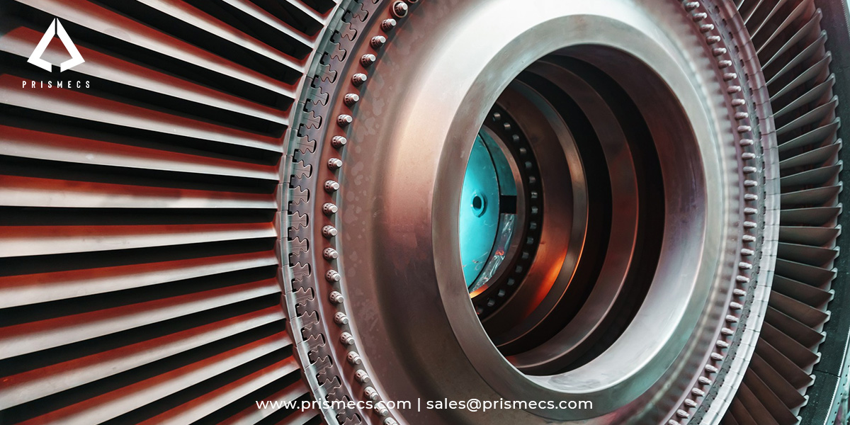
Gas turbine blades fail primarily through creep, thermal fatigue, hot corrosion, oxidation, and thermal barrier coating loss, and most of these begin when the blade's cooling protection degrades. Turbine blades account for more than 42% of gas turbine failures, making blade condition the single largest driver of hot-section reliability.
This guide covers how blade cooling actually works, the main failure mechanisms and what triggers them, why coating loss accelerates everything, how blocked cooling passages destroy blades from the inside, the inspection methods that detect damage early, and how to decide between repair and replacement.
It is written for plant managers, turbine and reliability engineers, and O&M leaders responsible for hot-section condition, outage planning, and parts decisions.
How Gas Turbine Blade Cooling Actually Works
Gas turbine blades are cooled by compressor bleed air, not by any liquid coolant, and that air is the only thing keeping the blade below its melting point. Air is extracted from the later compressor stages at roughly 450 to 650°C and routed through internal passages inside each blade.
That relatively cooler air brings blade metal temperature down to around 1000°C, which is the range where nickel-base superalloys operate reliably. First-stage blades sit in gas temperatures of roughly 2,400 to 2,800°F, well above the melting point of the alloy itself, so the cooling system is not an efficiency feature. It is what makes the blade survivable.
Cooling works through two families of technique. Internal cooling uses convection and impingement through serpentine multi-pass passages with trip strips. External cooling uses film, effusion, and transpiration cooling, ejecting air through surface holes to form a protective boundary layer between the blade and the hot gas.
There is a cost to this protection. Bleed air is diverted from the cycle and does no useful work, so designers target minimal coolant use, typically 3 to 5% of compressor flow. Every degradation that forces more cooling, or wastes what is there, costs output.
The Main Blade Failure Mechanisms
Gas turbine blade failures are driven by a small set of well-documented mechanisms, and most real failures involve several acting together rather than one in isolation. Recognizing which mechanism is present determines whether a blade is repairable.
The mechanisms compound. Published failure analyses of first and second-stage blades found the root cause was a combination of oxidation, creep, and fatigue damage rather than any single mode. Coating damage was shown to promote overheating, which in turn accelerated creep and caused rafting of the gamma-prime precipitates that give the superalloy its strength.
Centrifugal loading is the constant background stress. A blade carries enormous rotational force at temperature, so any mechanism that weakens the alloy or thins the section is working against a load that never lets up.
Why TBC Loss Is the Failure That Starts the Others
Thermal barrier coating loss is the most consequential single degradation event on a turbine blade, because once the ceramic layer spalls, the superalloy underneath is immediately exposed to temperatures beyond its design limit. Coating condition, more than any other factor, determines remaining blade life.
TBCs are thin. A typical ceramic topcoat runs roughly 0.015 to 0.030 inches, commonly partially stabilized zirconia, with thermal conductivity around 1.3 W/mK. That thin layer delivers a temperature drop of roughly 100 to 200°C at the blade surface, which is the entire margin between safe operation and accelerated damage.
The failure pathway is well characterized. The primary mechanisms are growth of the thermally grown oxide (TGO) at the bond-coat interface and bond-coat oxidation. As the TGO thickens through thermal cycling, interfacial stress builds until the topcoat delaminates and spalls.
The service reality is worse than the design intent. Thermal barrier coatings for gas turbine blades are designed to last around 48,000 hours, but field experience indicates only about 40% of that is typically realized, with breakdown and delamination observed after roughly 18,000 hours at 1850°F. Extending that interval toward the design figure has been estimated to save more than USD 1 million over the life of a single blade row.
Blocked Cooling Passages: The Failure You Cannot See
Blocked internal cooling passages destroy blades from the inside, and because the blockage is invisible during external inspection, the damage is usually discovered only after cracking appears. This is one of the most under-recognized failure pathways in hot-section operation.
A documented failure analysis of a GE Frame 9 blade illustrates the mechanism precisely. After 66,000 hours of operation the blade fractured, and investigation found its internal cooling channels had become blocked. CFD reconstruction showed the blockage produced roughly a 100°C increase in blade temperature, along with 5 µm of TGO growth and measurable change in coating porosity.
The chain is straightforward and fast. Restricted coolant flow raises metal temperature, higher metal temperature accelerates TGO growth and coating degradation, coating loss exposes the substrate, and oxidation and creep then take the blade to fracture. A blade can be visually acceptable on the surface while this progresses internally. That gap between surface appearance and internal condition is exactly the case for monitoring parameters that reveal degradation before it is visible.
Film cooling hole blockage and distortion produce a related effect externally, removing the protective air film from local areas and creating hot spots that concentrate thermal fatigue damage.
How to Inspect Blades for Cooling and Coating Damage
Blade condition is assessed through remote visual inspection with a borescope in situ, supplemented by surface and subsurface NDT when blades are accessible or removed. The inspection method depends on whether the turbine is opened and what mechanism is suspected.
The methods that apply to hot-section blades:
- Borescope remote visual inspection (RVI): the primary in-situ method, performed through casing access ports between runs, detecting coating spallation, cracks, corrosion, cooling hole condition, and foreign object damage.
- Eddy current testing (ET): effective for surface and near-surface cracking, and it can be performed in situ through casing portholes without removing the turbine from its casing.
- Fluorescent penetrant inspection (FPI): the standard surface-crack method for nickel-base superalloy blades once removed, since these alloys are non-ferromagnetic and magnetic particle testing does not apply to them.
- Metallographic analysis and CT scanning: destructive and volumetric methods used in root-cause investigation after removal.
Consistency of grading is the practical challenge. A single borescope inspection can generate several hundred images across dozens of access ports, and each must be graded against the same severity standard to distinguish a hairline crack that can wait for the next scheduled outage from one requiring immediate shutdown.
NDT personnel qualification is governed by ASNT SNT-TC-1A in North America and ISO 9712 internationally. For reliability tracking, ISO 14224 provides the standardized taxonomy for recording failure and maintenance data, which is what makes blade failure history usable across a fleet.
Repair or Replace: Making the Decision
The repair-versus-replace decision on a turbine blade depends on the damage mechanism, its depth, and remaining creep life, not on visual severity alone. Some mechanisms are recoverable through refurbishment; others mean the blade is finished.
The economics favor early detection. A blade caught at the coating-loss stage can often be refurbished at a fraction of replacement cost, while the same blade left in service until oxidation and creep have progressed becomes scrap and may take downstream hardware with it. This is why coating condition assessment during scheduled inspections carries such high return.
Repair capability is also finite. Refurbishment is bounded by OEM repair limits and by how many times a given blade has already been processed, so a repair-versus-replace policy should account for cumulative repair history, not just current condition. Where the disposition is replacement, frame-specific coverage and verified traceability become the criteria for choosing a hot-gas-path parts supplier.
How Prismecs Supports Hot-Section Reliability
Prismecs supports gas turbine hot-section reliability through O&M, inspection support, and OEM-agnostic sourcing of hot-gas-path components, so operators can act on blade findings rather than just record them. Prismecs supplies and maintains turbine hardware; it does not design blade cooling systems or perform CFD blade optimization.
The Prismecs capability set for hot-section condition:
- O&M and inspection support: condition monitoring and maintenance execution across mixed-vendor turbine fleets, aligned to inspection intervals.
- Hot-gas-path parts sourcing: OEM-genuine and qualified equivalent blades, nozzles, shrouds, liners, and transition pieces, verified with material certification and dimensional inspection.
- Outage-aligned supply: parts staged to the inspection window so a blade finding does not extend the outage while hardware is sourced.
- 24/7 emergency procurement: rapid sourcing when an inspection reveals damage requiring immediate replacement.
- Turnkey execution: installation and commissioning support, so sourcing and field work sit with one accountable partner.
The differentiator is closing the loop between finding and fix. Inspection tools identify damage and research explains mechanisms, but neither sources the replacement blade or installs it. Prismecs connects the condition finding to verified hardware and the crew to fit it.
Frequently Asked Questions
Why do gas turbine blades fail?
Gas turbine blades fail through creep, thermal fatigue, hot corrosion, oxidation, erosion, and thermal barrier coating spallation, usually acting in combination rather than alone. Turbine blades account for more than 42% of gas turbine failures. Most failure sequences begin when cooling protection degrades, allowing metal temperature to exceed design limits and accelerating every other mechanism.
What cools a gas turbine blade?
Compressor bleed air cools gas turbine blades, not liquid coolant. Air is extracted from the later compressor stages at roughly 450 to 650°C and routed through internal serpentine passages and out through film cooling holes. This reduces blade metal temperature to around 1000°C. Designers limit coolant use to roughly 3 to 5% of compressor flow, because bleed air does no useful work in the cycle.
What is TBC spallation and why does it matter?
Thermal barrier coating spallation is the separation of the ceramic topcoat from a turbine blade, typically after repeated thermal cycling. It matters because the coating provides a 100 to 200°C temperature drop, and once it is gone the nickel superalloy substrate faces temperatures beyond design limits. The primary causes are thermally grown oxide growth at the bond-coat interface and bond-coat oxidation.
How long do thermal barrier coatings last?
Thermal barrier coatings on gas turbine blades are designed for around 48,000 hours, but field experience indicates only about 40% of that is typically realized. Breakdown and delamination have been observed after roughly 18,000 hours at 1850°F. Extending coating life toward the design interval has been estimated to save more than USD 1 million over the life of a single blade row.
How are turbine blades inspected for damage?
Turbine blades are inspected primarily by borescope remote visual inspection through casing access ports, which detects coating loss, cracking, corrosion, and cooling hole condition without opening the machine. Eddy current testing can also be performed in situ through portholes. Fluorescent penetrant inspection is used on removed blades, since nickel superalloys are non-ferromagnetic and magnetic particle testing does not apply.
Can a damaged turbine blade be repaired or must it be replaced?
It depends on the mechanism and depth. Coating spallation with an intact substrate is typically repairable by stripping, inspecting, and recoating, and limited surface cracking may be weld or braze repaired within OEM limits. Creep elongation beyond limits and deep thermomechanical fatigue cracks require replacement, because microstructural damage and lost structural integrity are not recoverable.
Why Blade Condition Is a Reliability Decision
Blade condition management is a reliability and cost decision, not a maintenance formality, because the hot section drives the majority of gas turbine failures and coating loss quietly sets the timetable for everything that follows. The mechanisms are documented, the inspection methods are established, and the difference between a refurbished blade and a scrapped row is usually how early the damage was found.
Operators managing hot-section risk need a partner who can support inspection, source verified replacement hardware, and execute the work within the outage window. That is the Prismecs model: OEM-agnostic sourcing backed by turnkey O&M, built around turbine availability.
To source hot-gas-path components or align blade inspection findings with parts supply, call +1 (888) 774-7632 or email sales@prismecs.com.
Tags: gas turbine blade failure thermal barrier coating spallation hot gas path inspection turbine blade creep borescope inspection
recent posts
O&M Services
15 minutes read
Writing a Power Plant O&M RFP That Gets Comparable Bids
Write a power plant O&M RFP every bidder must price the same way. Get the pricing template, data room checklist and weighted scorecard that expose eve...
EPCM Services
19 minutes read
25 Questions to Ask a Power Plant EPC Contractor Before You Sign
Most lists of questions to ask an EPC contractor stop at the question. Get why each matters, the strong answer, the red-flag reply and a weighted bid...
Gas Turbines
19 minutes read
Dual-Fuel Gas Turbines: How Gas-and-Liquid Fuel Flexibility Works
A dual-fuel gas turbine switches from natural gas to diesel at load, but most failures start in idle oil lines. Get transfer steps and coking fixes be...
Power Utilities
18 minutes read
Temporary and Bridge Power for Industrial Facilities: When and How to Use It
Planning bridge power past 12 months? Under EPA rules your generators may be stationary from day one. Check Tier 4, NSPS KKKKa and SPCC triggers befor...