
A gas turbine compressor has two failure modes, they are routinely confused, and one usually warns you about the other.
Rotating stall is a localized breakdown of airflow that travels around the compressor annulus while the machine keeps running. It reduces output, excites blades and causes fatigue damage.
Surge is a full-machine flow reversal. It is violent, it happens in a fraction of a second, and it imposes severe mechanical stress on rotor blades, bearings and combustor components.
The operationally useful fact is that surge is typically preceded by a rotating stall. The transition is often a gradually developing instability rather than an instant event, which means the expensive failure usually announces itself first, on instruments you already have.
This guide covers what the compressor does, what makes it unstable, what protects it, how to see trouble coming, and when opening the machine is justified.
What the Compressor Does
The compressor raises the pressure of ambient air before it reaches the combustor, and it consumes a large share of the turbine's own output to do it.
Air enters, passes through successive compression stages, and leaves at high pressure and elevated temperature. That compressed air mixes with fuel in the combustor, burns, and expands through the turbine.
The compressor and turbine sit on a common shaft, forming a direct mechanical link. The turbine drives the compressor and the generator from the same rotation.
Roughly half to two-thirds of the turbine's gross work goes into driving its own compressor. That is why a small loss in compressor efficiency produces a disproportionate loss in net output, and why compressor condition is an economic issue rather than a mechanical curiosity.
Bleed air
Beyond supplying the combustor, the compressor provides bleed air, extracted from intermediate stages for turbine blade cooling, bearing seal pressurization, anti-icing and surge protection during starts. Bleed air is not waste. It is a designed extraction with a defined effect on the compressor's operating point.
Because the common shaft couples the two machines, bearing condition on that shaft directly affects sustained performance. See our analysis of gas turbine bearing failure causes. For how the turbine compares with reciprocating machines, see our turbine versus combustion engine comparison.
Axial and Centrifugal Compressors
Two compressor architectures exist, and industrial gas turbines use axial compressors almost exclusively.
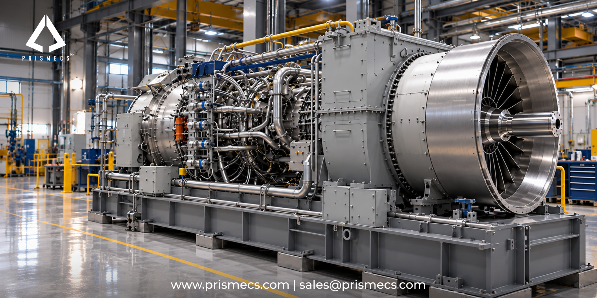
- An axial-flow compressor moves air along a path parallel to the shaft, through alternating stages of rotating blades and stationary vanes. It achieves high efficiency and high overall pressure ratio through many stages in series, and it dominates large industrial turbines and utility-scale power generation.
- A centrifugal-flow compressor accelerates air outward from the centre of rotation using an impeller, then decelerates it through a diffuser to convert velocity into pressure. It achieves a high pressure rise in very few stages, which suits small turbines, microturbines and auxiliary machines.
A common error worth avoiding: an impeller is not the same thing as a rotor, and a diffuser is not the same thing as a stator. Those are the centrifugal and axial equivalents of each other, not interchangeable terms. Specifying the wrong one in a parts enquiry produces a quotation for the wrong machine.
Centrifugal designs use single-entry impellers for simpler ducting, or double-entry impellers with a plenum chamber where higher airflow is needed at the cost of ducting complexity.
Inside an Axial Compressor
An axial compressor is a series of stages, each consisting of one row of rotating blades followed by one row of stationary vanes, and each contributing a modest pressure rise.
Rotor blades add energy to the air, increasing both its velocity and its pressure. Stator vanes then decelerate the flow, converting velocity into further pressure rise, and redirect the air into the correct angle for the next rotor row.
Each axial stage typically produces a pressure ratio of around 1.25:1. That is deliberately modest, because a larger rise per stage narrows the range of conditions over which the stage remains aerodynamically stable.
Why there are so many stages
To reach an overall pressure ratio of 20:1 at roughly 1.25:1 per stage requires many stages in series. Modern industrial gas turbines operate at overall compressor pressure ratios ranging from 15:1 to over 40:1, depending on turbine class and application, which means compressor sections of fifteen stages and upward.
Higher pressure ratios improve thermal efficiency and power density. They also demand tighter manufacturing tolerances, advanced blade materials and more sophisticated surge control, because the stable operating window narrows as the ratio rises.
The angle of attack is everything
Each blade and vane is designed for a specific airflow angle at a specific speed. When the actual angle deviates far enough from the design angle, flow separates from the blade surface and the stage stalls. Everything in the sections that follow comes back to that single relationship.
Rotating Stall
Rotating stall is a localized flow separation that forms a stall cell extending axially through the compressor and travels around the annulus while the machine continues to run.
It does not stop the machine. That is what makes it dangerous, because a compressor can operate in rotating stall while an operator sees only reduced performance.
Rotating stall reduces the compressor's output, measured as annulus-averaged pressure rise and mass flow. A machine in stall delivers less air at lower pressure, which shows up as reduced power and elevated exhaust temperature.
Why it damages the machine
The stall cell rotates at a fraction of rotor speed, which means each blade passes in and out of the stalled region on every revolution. That produces a cyclic aerodynamic excitation at a frequency unrelated to rotor speed, which is precisely the condition that drives high-cycle fatigue in blading.
If rotating stall is undetected and allowed to continue, combustor temperatures and vibratory stresses in the compressor can become high enough to damage the turbine. The damage accumulates rather than appearing at once.
In centrifugal machines
Rotating stall in a fixed-speed centrifugal compressor is predominantly located in the diffuser, rather than in the impeller, and it can be remediated with a variable geometry diffuser that adjusts flow angles at part load.
Surge
Surge is a complete breakdown of stable flow through the compressor, producing rapid axial flow reversal and violent pressure oscillation throughout the machine.
Where rotating stall is localized and rotating, surge involves the entire compression system. Flow reverses, pressure collapses, forward flow re-establishes, and the cycle repeats until the control system intervenes or the machine trips.
What it does
Surge imposes severe mechanical stress on rotor blades, bearings and combustor components. A single event can cause blade damage requiring inspection; repeated events cause cumulative damage that ends in blade liberation.
The relationship to stall
Surge is typically preceded by a rotating stall. As the operating point moves from the stall region toward full surge, the transition may not be immediate but a gradually developing instability, sometimes described as incipient surge.
That relationship is the whole operational argument of this article. A precursor that develops over time is a precursor you can act on.
But it is not universal. A compressor can enter surge directly, and where it does, the control system has no opportunity to sense the precursor stall condition and no chance to take avoiding action. Protection systems therefore have to be designed for both cases: detect and correct the precursor where it exists, and survive the event where it does not.
Surge Margin and the Compressor Map
Surge margin is the distance between where the compressor is operating and where it becomes aerodynamically unstable, and it is a design trade against efficiency.
A compressor map plots pressure ratio against mass flow at a series of rotor speeds. It is produced by physical test: when a manufacturer designs a new compressor, it varies flow rates and rotor speeds to measure pressure ratio and efficiency, and to determine the compressor surge line.
The surge line is the locus of points beyond which stable operation breaks down. The operating line is where the machine actually runs. The gap between them is the margin.
The numbers
Stall margin is the ratio between the peak pressure rise the compressor can achieve and the pressure rise at the operating point. In gas turbine engines used to power aircraft, stall margins of 15 to 30 percent are common.
The trade nobody escapes
Peak compressor efficiency sits close to the surge line. Operating at less than peak pressure rise carries a reduction in efficiency and performance, which means margin and efficiency are traded directly against each other.
A design objective is to incorporate enough margin to absorb the disturbances the machine is expected to encounter, without giving away more efficiency than necessary. Every percent of margin has a fuel cost, and every percent given up has a risk cost.
Surge Control Line and Surge Limit Line
Control systems distinguish the Surge Limit Line (SLL), where instability actually begins, from the Surge Control Line (SCL), a deliberately conservative boundary at which protective action is triggered. Widening the gap between them increases protection and reduces available operating range.
What Causes Compressor Instability
Instability arises when the airflow angle at the blades deviates far enough from the design angle, and there are six routine causes.
- Upstream flow disturbance. Distorted or non-uniform inlet flow changes the angle of attack at the first stage. Inlet filter damage, partial blockage or a disturbed inlet plenum all qualify.
- Downstream back pressure. A sudden rise in back pressure reduces air velocity through the compressor and increases the inlet angle, often the result of a blockage in the combustor or turbine. Fuel system faults and hot section damage both produce it.
- Compressor fouling. Deposits on blading change blade profiles and reduce mass flow, moving the operating point toward the surge line. Fouling consumes surge margin continuously and silently, which makes it the connection between routine degradation and a catastrophic failure mode. For fouling, washing and the recovery economics, see our guide to gas turbine casings, clearance and fouling.
- Blade damage and erosion. Foreign object damage, erosion in dusty environments and tip clearance growth all alter blade aerodynamics. The effect is permanent and not recoverable by washing.
- Control system faults. A stuck or mis-scheduled inlet guide vane actuator, or a bleed valve that fails to open on acceleration, removes the protection the machine depends on during the most vulnerable part of its cycle.
- Rapid load or fuel changes. Fast acceleration raises rotor speed faster than airflow establishes, which is precisely why start sequences include specific protective schedules. Combustion tuning affects this directly; see our overview of DLN tuning services.
Ambient conditions
Cold, dense air raises pressure ratio for a given speed, moving the operating line toward the surge line. This is why some machines use inlet bleed heat during cold ambient conditions, trading a small efficiency loss for margin.
Protection Systems
Six mechanisms protect a compressor from stall and surge, and most of them act during startup and part load rather than at full load.
- Inlet guide vanes (IGV) direct air into the first compressor stage at the correct angle. Variable inlet guide vanes reposition to regulate airflow and maximise performance across the operating range.
- Variable stator vanes control the angle of flow onto the rotor rows at intermediate stages, maintaining the correct angle of attack as speed and flow change.
- Compressor bleed valves increase airflow through the front stages by dumping air from intermediate stages, which unloads the front of the machine during acceleration.
- Casing treatments, grooves or slots machined into the casing over the blade tips, enhance stability at the tip where stall typically initiates.
- Tip clearance control maintains the gap between blade tips and casing, which affects both efficiency and stability.
- Anti-surge control systems monitor the operating point against the Surge Control Line and take protective action before the limit is reached.
Why startup is the dangerous window
During acceleration the compressor passes through a speed range where rotating stall is likely. The control logic is specific and deliberate.
At a speed just below the rotating stall initiation speed, the inlet guide vane is modulated open. Opening the IGV as far as permitted extends rotating stall initiation to a higher speed while maintaining adequate surge margin. Bleed valves are opened at the same time, at low compression ratios where surge margin is inadequate, and closed once the machine reaches or exceeds its design condition.
Every start puts the machine through this sequence. A cycling plant passes through the stall-prone region far more often than a base-load plant, which is one reason peaking duty is harder on compressors than running hours alone suggest.
The surge response sequence
When surge is detected, a typical control response opens the bleed valves, energizes the ignition system, and rapidly reduces fuel flow. The fuel dip is what breaks the cycle, by removing the back pressure sustaining the flow reversal.
If a bleed valve sticks
A bleed valve that fails closed during acceleration removes margin at exactly the point the machine needs it. Bleed valve stroke testing belongs in the preventive maintenance programme, and its absence is a common finding after a surge event.
Detection: What You Can Actually See
Surge is easy to detect and rotating stall is not, which means the precursor is harder to catch than the event it predicts.
Detection of rotating stall with the standard instrumentation used for antisurge control is more challenging than surge detection. Existing surge detection methods in control systems use thermodynamic measurements such as flow, pressure and temperature, and their rates of change. Those respond well to a violent event and poorly to a developing one.
The vibration signature
Both surge and rotating stall cause subsynchronous shaft vibration, meaning vibration at a frequency below rotor speed.
Rotating stall can be detected when the subsynchronous vibration component exceeds a threshold level and the compressor is operating in a region of the compressor map where rotating stall is likely. That region is delineated by minimum rotational speed, proximity to the Surge Control Line, compressor discharge pressure and compressor flow.
Vibration alone is not enough, and map position alone is not enough. The detection requires both together, which is why generic vibration alarms miss rotating stall.
ISO 20816 governs the measurement and evaluation of machine vibration, and it is the reference for specifying monitoring on rotating equipment.
The operator's signature
What an operator can observe without specialist instrumentation:
- Compressor discharge pressure fluctuates rather than holding steady at constant load.
- Exhaust temperature spread widening, which indicates disturbed or uneven flow.
- Output falling at constant ambient and constant fuel, beyond what fouling alone explains.
- An audible bark, rumble or repeated cough, particularly during acceleration or load change.
- Subsynchronous vibration rising without a corresponding change at rotor frequency.
- Any two of these together justify investigation. A machine that barks on every start is telling you its margin has gone.
What to specify in monitoring
Continuous vibration monitoring with spectral analysis rather than overall level alone, so that sub synchronous content is visible. Compressor discharge pressure and temperature trended rather than alarmed. Exhaust spread trended by thermocouple. And the compressor operating point plotted against the map, which almost no plant does and which is what turns raw data into a margin position.
For matching monitoring method to failure mode across the plant, see our comparison of predictive versus preventive maintenance.
When to Open the Machine
A borescope inspection is justified when instability has been observed, when performance loss does not recover after washing, or when a surge event has occurred.
A borescope inspection examines compressor blading and internal surfaces through access ports without full disassembly. It shows blade tip rubs, leading edge damage, erosion, deposit build-up, coating loss and foreign object damage.
The four triggers
- After any confirmed surge event. A single surge can cause blade damage that is invisible in performance data and fatal over the following months.
- When performance loss does not recover after washing. If output and heat rate do not return after an offline wash, the loss is mechanical rather than fouling, and mechanical losses are found by looking.
- When subsynchronous vibration has been observed in a stall-prone region of the map, even without a trip.
- When a foreign object event is suspected, including inlet filter failure or debris ingestion.
What a finding means
Tip rubs indicate a clearance problem and point at the casing. Leading edge damage points at ingestion. Uniform erosion points at filtration. The location of the damage tells you which upstream system failed, which is why the inspection is a diagnostic rather than a condition survey.
Warranty, insurance and reporting
Operating a machine with known instability outside manufacturer guidance can affect warranty position on a unit still in term. Machinery breakdown insurers assess maintenance records and response to known conditions, and a documented surge event with no subsequent inspection is a claim problem.
Surge events and the outages they cause are reportable as forced outages, and they feed the forced outage rate that capacity markets and O&M contracts use. For how that reporting works, see our guide to power plant O&M metrics and contracts.
If surge recurs
Repeated surge is a system problem, not an event. The cause is upstream: fouling that has not been addressed, a control schedule that no longer matches the machine's condition, a filtration failure, or hot section damage creating back pressure. For structured root cause work, see our guide to gas turbine troubleshooting and unplanned downtime, and for scheduling the intervention, our outage planning guide.
Governing Standards
Three standards govern compressor specification, performance testing and vibration monitoring on industrial gas turbines.
Name ASME PTC 22 in any performance guarantee. Compressor degradation is only arguable against a baseline established by a recognized test method, and a guarantee with no test code behind it cannot be enforced.
Outside the United States
API, ASME and ISO standards apply internationally. National grid codes differ, and some impose frequency response and ramping obligations that increase cycling, which increases the number of times the machine passes through its stall-prone startup region.
How Requirements Vary by Machine and Site
The physics is constant. What changes is how much margin the machine has and how fast it is consumed.
- Aeroderivative machines run at high pressure ratios with tight margins and multiple spools, and they use extensive variable geometry to maintain stability across a wide operating range. They also start frequently, which puts them through the stall-prone acceleration region often.
- Heavy-duty frame machines have larger compressors, greater thermal inertia and typically lower pressure ratios than the highest-rated aeroderivative. They cycle less and their instability risk concentrates in fouling and control schedule drift.
- Small turbines and microturbines frequently use centrifugal compressors, where rotating stall concentrates in the diffuser and variable geometry diffusers are the remedy.
- Peaking and cycling duty consumes margin faster because every start passes through the region the IGV and bleed schedules exist to protect. Base-load machines encounter it a handful of times a year.
- Hot and dusty sites foul and erode faster, and erosion is not recoverable. Filtration specification determines the fouling rate and therefore the rate at which margin is consumed. For ambient derate and site rating, see our guide to gas turbine power stations and ISO rating.
- Coastal sites face salt aerosol, which is hygroscopic and fouls aggressively, and which also drives hot section corrosion that can create the downstream back pressure that triggers surge.
What Prismecs Does
Prismecs installs, commissions, operates and maintains aeroderivative gas turbine plant, and supplies equipment and components for power generation assets.
Delivered project scope includes eight TM2500 dual-fuel units totaling 260 MW at Birr, Switzerland, online in six months with a new 220 kV interconnection; four TM2500 units totalling 110 MW at Duqm, Oman, kept grid-ready with resident O&M crews, CMMS and parts support; an LM2500XPRESS plant at Miaoli, Taiwan delivered in ten months; three LM6000PC units adding 150 MW of fast-start reserve; and an LM6000 fleet decommissioned in Norway, transported and recommissioned at a new site.
The TM2500, LM2500 and LM6000 are aeroderivative machines with axial compressors and extensive variable geometry, which is the class this article describes throughout.
Capability spans O&M services for the operating phase, power generation asset services for the equipment, I&C services for controls and instrumentation including IGV and bleed valve systems, ready-to-ship equipment inventory for components, and technology and consulting for performance assessment.
Prismecs is OEM-agnostic, which on a compressor condition assessment matters because the party recommending the work is not the party selling the blades.
Apply this article's criteria to any provider, including us. Ask whether the compressor operating point will be plotted against the map, not just alarmed. Ask whether vibration monitoring resolves sub synchronous content. Ask which ASME code any performance baseline is established under. Ask what the inspection findings mean for the upstream system.
To discuss compressor performance, an instability investigation or component supply, send your machine model, operating hours, recent performance trend and the symptom you are seeing to sales@prismecs.com or call +1 (888) 774-7632.
Frequently Asked Questions
What does a compressor do in a gas turbine?
It raises the pressure of ambient air before the combustor, delivering compressed air for combustion and bleed air for turbine blade cooling, seal pressurization and surge protection. The compressor and turbine share a common shaft, and roughly half to two-thirds of the turbine's gross work drives the compressor. That is why a small loss in compressor efficiency produces a disproportionate loss in net output.
What is the difference between rotating stall and surge?
Rotating stall is a localized flow separation forming a stall cell that travels around the compressor annulus while the machine keeps running, reducing pressure rise and mass flow and exciting blades at a frequency unrelated to rotor speed. Surge is a complete breakdown of flow through the entire compression system, producing rapid axial flow reversal and violent pressure oscillation that stresses rotor blades, bearings and combustor components.
Does rotating stall always precede surge?
Usually, but not always. Surge is typically preceded by rotating stall, and the transition from stall toward full surge is often a gradually developing instability rather than an instant event. However, a compressor can enter surge directly, and where it does the control system has no opportunity to sense the precursor condition. Protection has to cover both the developing case and the sudden one.
What is the surge margin?
The distance between the compressor's operating line and its surge line on the compressor map. Stall margin is the ratio between peak achievable pressure rise and pressure rise at the operating point. Stall margins of 15 to 30 percent are common in aircraft gas turbines. Because peak efficiency sits close to the surge line, margin and efficiency are traded directly against each other.
What causes compressor surge?
Airflow angle at the blades deviating far enough from the design angle. Causes include upstream flow disturbance from filter damage or distorted inlet flow, sudden downstream back pressure often from a blockage in the combustor or turbine, compressor fouling reducing mass flow, blade damage and erosion, control faults such as a stuck inlet guide vane or a bleed valve failing to open, and rapid load or fuel changes.
How does compressor fouling cause surge?
Deposits on blading alter blade profiles and reduce mass flow, which moves the compressor's operating point toward the surge line. Fouling consumes surge margin continuously and silently, which makes it the link between routine degradation and a catastrophic failure mode. A machine that has lost margin to fouling tolerates a smaller disturbance before becoming unstable than the same machine when clean.
What are inlet guide vanes and what do they do?
Inlet guide vanes direct air into the first compressor stage at the correct angle, and variable inlet guide vanes reposition to regulate airflow across the operating range. During startup the IGV is modulated open just below the rotating stall initiation speed, which extends stall initiation to a higher speed while maintaining adequate surge margin. Variable stator vanes perform the equivalent function at intermediate stages.
Why do compressor bleed valves open during startup?
To increase airflow through the front stages by dumping air from intermediate stages, unloading the front of the compressor during acceleration. Bleed valve control opens the valves at low compression ratios where surge margin is inadequate, and closes them once the machine reaches or exceeds its design condition. A bleed valve that fails closed during acceleration removes margin at the point it is most needed.
How do I detect a rotating stall?
Through sub synchronous vibration combined with map position. Rotating stall is detected when the subsynchronous vibration component exceeds a threshold and the compressor is operating in a region of the map where stall is likely, delineated by minimum rotational speed, proximity to the Surge Control Line, discharge pressure and flow. Vibration alone and map position alone are both insufficient, which is why generic vibration alarms miss it.
What warning signs can an operator see without specialist instrumentation?
Compressor discharge pressure fluctuates rather than holding steady at constant load. Exhaust temperature spread widening. Output falling at constant ambient and constant fuel beyond what fouling explains. An audible bark, rumble or repeated cough, particularly on acceleration. And sub synchronous vibration rising without a corresponding change at rotor frequency. Any two together justify investigation.
What damage does a surge event cause?
Severe mechanical stress on rotor blades, bearings and combustor components. A single event can cause blade damage invisible in performance data and consequential months later. If instability is undetected and allowed to continue, combustor temperatures and vibratory stresses can become high enough to damage the turbine. Repeated surge produces cumulative damage ending in blade liberation.
When should I borescope a compressor?
After any confirmed surge event. When performance loss does not recover after an offline wash, because the loss is then mechanical rather than fouling. When sub synchronous vibration has been observed in a stall-prone region of the map, even without a trip. And when a foreign object event is suspected, including inlet filter failure or debris ingestion.
What is the difference between an axial and a centrifugal compressor?
An axial compressor moves air parallel to the shaft through alternating rotor blade and stator vane stages, achieving high efficiency and high overall pressure ratio, and dominates large industrial turbines. A centrifugal compressor accelerates air radially outward through an impeller and decelerates it in a diffuser, achieving high pressure rise in a few stages, which suits small turbines and microturbines.
What pressure ratios do gas turbine compressors achieve?
Modern industrial gas turbines operate at overall compressor pressure ratios from 15:1 to over 40:1, depending on turbine class and application, with each axial stage contributing approximately 1.25:1. The modest per-stage figure is deliberate, because a larger rise per stage narrows the range of conditions over which the stage remains aerodynamically stable. Higher overall ratios improve efficiency and demand more sophisticated surge control.
Tags: Gas Turbine Compressor Compressor Surge Rotating Stall Surge Margin Turbine Inspection
recent posts

O&M Services
15 minutes read
Writing a Power Plant O&M RFP That Gets Comparable Bids
Write a power plant O&M RFP every bidder must price the same way. Get the pricing template, data room checklist and weighted scorecard that expose eve...

EPCM Services
19 minutes read
25 Questions to Ask a Power Plant EPC Contractor Before You Sign
Most lists of questions to ask an EPC contractor stop at the question. Get why each matters, the strong answer, the red-flag reply and a weighted bid...
Gas Turbines
19 minutes read
Dual-Fuel Gas Turbines: How Gas-and-Liquid Fuel Flexibility Works
A dual-fuel gas turbine switches from natural gas to diesel at load, but most failures start in idle oil lines. Get transfer steps and coking fixes be...

Power Utilities
18 minutes read
Temporary and Bridge Power for Industrial Facilities: When and How to Use It
Planning bridge power past 12 months? Under EPA rules your generators may be stationary from day one. Check Tier 4, NSPS KKKKa and SPCC triggers befor...