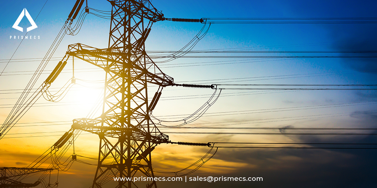
Industrial electrical power infrastructure is the substation, switchgear, and distribution equipment that takes power from the utility connection or on-site generation and delivers it safely across a plant at usable voltages. Its design determines plant uptime, personnel safety, and how quickly a facility can energize.
This guide covers what industrial electrical infrastructure includes, how air-insulated and gas-insulated substations compare, the power system studies every project requires, the IEEE and NFPA standards that govern design and safety, and why long-lead equipment now drives project schedules more than engineering does.
It is written for plant managers, electrical and facilities engineers, and EPC and procurement leaders building or upgrading power infrastructure for industrial facilities, data centers, and generation assets.
Prismecs engineers, supplies, and maintains industrial electrical infrastructure. It works on customer-side substations, switchgear, and plant power systems rather than utility transmission line construction or residential distribution networks.
What Industrial Electrical Infrastructure Covers
Industrial electrical infrastructure covers everything between the point of supply and the plant loads: the substation, transformers, switchgear, protection systems, and distribution equipment inside the facility boundary. This is customer-side infrastructure, distinct from the utility transmission network that feeds it.
The core elements of an industrial power system:
- Substation: transformers, circuit breakers, disconnects, and the yard or enclosure housing them, stepping incoming voltage down to plant distribution levels.
- Switchgear: medium-voltage and low-voltage assemblies containing breakers, protective relays, and metering.
- Protection and control: relays, intelligent electronic devices (IEDs), and the automation layer that isolates faults.
- Distribution equipment: motor control centers (MCCs), panelboards, cable and bus systems feeding plant loads.
- Grounding and lightning protection: the ground grid and shielding that keep fault currents and surges from injuring personnel or damaging equipment.
Voltage classes define the scope. Industrial facilities typically receive power at high voltage between 69 kV and 230 kV, step it down to medium voltage at 4.16 kV to 34.5 kV for plant distribution, and step down again to 480 V or below for equipment. Each transition point is a substation or switchgear lineup that must be engineered, procured, and protected.
Air-Insulated vs Gas-Insulated Substations
Industrial substations are built either as air-insulated (AIS) or gas-insulated (GIS) designs, and the choice is driven primarily by available land, environmental exposure, and budget rather than electrical performance. Both are proven at industrial voltage levels.
Footprint is usually the deciding factor. A GIS installation can occupy a fraction of the land an equivalent AIS yard requires, which matters on congested industrial sites, and its sealed construction resists salt, dust, and corrosive atmospheres that degrade exposed AIS equipment. The trade-off is higher capital cost and more specialized maintenance.
Ownership boundaries should be settled early. Some industrial substations are utility-owned up to a defined point of delivery, while others are customer-owned in full, and that boundary determines who carries design approval, protection coordination, and maintenance responsibility.
The Power System Studies Every Project Requires
Every industrial electrical project requires a defined set of engineering studies before equipment is specified, because those studies determine equipment ratings, protection settings, and personnel safety requirements. Skipping or deferring them is the most common cause of rework and failed energization.
The studies that define a project:
- Load flow analysis: confirms voltages and equipment loading across the system under normal and contingency conditions.
- Short circuit study: establishes available fault current, which sets the interrupting rating every breaker and the withstand rating of every bus must meet.
- Protective device coordination: ensures the device nearest a fault operates first, isolating the smallest possible portion of the plant.
- Arc flash study: calculates incident energy and approach boundaries so personnel protective equipment can be specified and equipment labeled.
- Grounding study: verifies the ground grid limits touch and step potentials to safe levels using measured soil resistivity.
These studies feed each other in sequence. Short circuit results drive both coordination and arc flash calculations, and soil resistivity measurements drive grounding design, so performing them out of order or with assumed inputs produces equipment specifications that will not hold up at commissioning.
Standards Governing Industrial Substations and Electrical Systems
Industrial electrical infrastructure is governed by a specific family of IEEE, NFPA, and IEC standards, and citing them by exact designation is how design compliance is demonstrated to owners, insurers, and authorities having jurisdiction.
Two additional references apply where relevant. IEEE Std 142, the Green Book, covers grounding of industrial and commercial power systems more broadly than substation grids, and IEEE Std C37.122 governs gas-insulated substations specifically. Where distributed generation connects to the grid, IEEE Std 1547 governs the interconnection.
Grounding: Why IEEE Std 80 Decides Substation Safety
Substation grounding safety is determined by touch and step potentials, not by achieving a low ground resistance value, which is the most commonly misunderstood point in industrial electrical design. A low resistance reading does not by itself demonstrate a safe installation.
IEEE Standards states the principle directly: IEEE Std 80 is based on the safety criteria of acceptable touch and step potentials, and substations with low resistances are not an indication of safe design, nor is a substation with a high resistance necessarily an indication of an unsafe design. What determines safety is the soil resistivity, the magnitude of available fault current, and the physical layout of the ground grid itself.
The frequently quoted targets have a specific origin. Values of roughly 1 ohm or less for transmission substations and 1 to 5 ohms for distribution substations came from experience with typical United States substations in the 1950s, largely reflecting physical station size. They were adopted to support relay and fuse protection, not as safety criteria.
The practical consequence for an industrial owner is that a grounding design must begin with measured soil resistivity per IEEE Std 81 and a calculated fault current, then size the grid to hold touch and step voltages within tolerable limits. A grounding installation signed off on a resistance reading alone has not been verified against the standard.
Arc Flash and Electrical Safety Compliance
Arc flash protection in industrial electrical systems is governed by NFPA 70E, which OSHA recognizes as the consensus standard for electrical safe work practices. Compliance is enforced through OSHA regulations even though NFPA 70E is not itself a federal regulation.
The relationship is direct. According to OSHA, NFPA 70E was originally developed at OSHA's request and helps employers avoid injuries from shock, electrocution, arc flash, and arc blast while assisting compliance with OSHA 1910 Subpart S and 1926 Subpart K. OSHA's electrical safe work practice requirements appear at 29 CFR 1910.333.
The engineering output is what makes compliance possible. The arc flash boundary is defined as the distance at which incident energy equals 1.2 cal/cm2, the threshold for a second-degree burn, and incident energy is calculated using methods such as those in IEEE Std 1584. Those results produce the equipment labels and PPE requirements that make energized work decisions defensible.
Arc flash severity is driven by available fault current, clearing time, and working distance rather than by voltage alone, which is why a 480 V motor control center can present a serious hazard. Protection settings that reduce clearing time directly reduce incident energy, linking the coordination study to worker safety.
Long-Lead Equipment: The Real Schedule Risk
The critical path on most industrial electrical projects is now equipment procurement rather than engineering, because power transformers and switchgear carry lead times measured in years rather than months. Identifying long-lead items at the concept stage is what protects an energization date.
Transformers and medium-voltage switchgear are the usual constraints. A substation cannot be energized without its main transformer, so an order placed after detailed design is complete can leave a fully engineered project waiting on a single piece of equipment while construction crews demobilize.
The mitigations are procurement decisions, not engineering ones. Releasing long-lead purchase orders early against preliminary ratings, qualifying multiple manufacturers rather than a single source, and considering refurbished or surplus units where specifications permit all compress the schedule.
This is why equipment sourcing belongs inside the project team. When the engineering firm, the equipment supplier, and the construction contractor are three separate organizations, long-lead risk sits in the gaps between them, and it surfaces as schedule slip late in the project when options have narrowed.
How Prismecs Delivers Industrial Electrical Infrastructure
Prismecs delivers industrial electrical infrastructure by combining electrical engineering, equipment sourcing, and lifecycle O&M under one accountable partner, which is what keeps long-lead procurement from becoming schedule risk. The scope is customer-side power infrastructure for industrial facilities, data centers, and generation assets.
The Prismecs capability set for electrical infrastructure:
- Substation and switchgear projects: engineering and delivery of medium and high-voltage substations, switchgear lineups, and plant distribution systems.
- OEM-agnostic equipment sourcing: transformers, switchgear, breakers, and protection equipment sourced across multiple qualified manufacturers through eINDUSTRIFY, including long-lead and ready-to-ship options.
- Generation and DER interconnection: electrical infrastructure connecting on-site generation, distributed energy, and storage to plant systems and the grid.
- I&C and substation automation: protection, control, and monitoring integration using standard substation communication protocols.
- O&M and emergency response: maintenance across electrical assets and 24/7 sourcing when a transformer or breaker failure threatens plant availability.
The differentiator is coverage across engineering, equipment, and operation. Engineering firms design but do not procure at scale, contractors build but do not operate, and equipment suppliers ship but do not commission. Prismecs carries all three, which closes the handoffs where industrial electrical projects usually lose time.
Frequently Asked Questions
What does industrial electrical infrastructure include?
Industrial electrical infrastructure includes everything between the point of supply and the plant loads: the substation with its transformers and breakers, medium and low-voltage switchgear, protective relays and IEDs, motor control centers, cable and bus distribution, and the grounding and lightning protection systems. It is customer-side infrastructure, distinct from the utility transmission network that supplies the facility.
What is the difference between AIS and GIS substations?
An air-insulated substation (AIS) separates live equipment by air clearances in an open yard, offering lower capital cost and simpler maintenance access where land is available. A gas-insulated substation (GIS) encloses live parts in insulating gas within compact housings, occupying a fraction of the footprint and resisting salt, dust, and corrosive atmospheres, at higher capital cost and with more specialized maintenance.
What power system studies does an electrical project need?
An industrial electrical project needs load flow analysis, a short circuit study, protective device coordination, an arc flash study, and a grounding study. Short circuit results set equipment interrupting and withstand ratings and feed both coordination and arc flash calculations, while measured soil resistivity drives grounding design. Performing them out of sequence produces equipment specifications that fail at commissioning.
Does a low ground resistance mean a substation is safely grounded?
No. IEEE Std 80 is based on acceptable touch and step potentials, and IEEE Standards states that substations with low resistances are not an indication of safe design, nor is high resistance necessarily unsafe. Safety is determined by soil resistivity, available fault current, and the physical layout of the ground grid. Design should start from measured soil resistivity and calculated fault current.
What standards govern arc flash safety in industrial plants?
NFPA 70E, the Standard for Electrical Safety in the Workplace, governs arc flash safe work practices, and OSHA recognizes it as the consensus standard, having originally requested its development. It supports compliance with OSHA 1910 Subpart S and 1926 Subpart K. The arc flash boundary is where incident energy reaches 1.2 cal/cm2, calculated using methods such as IEEE Std 1584.
Why are transformer lead times a project risk?
Because a substation cannot be energized without its main transformer, and power transformers and medium-voltage switchgear now carry lead times measured in years. When long-lead orders are placed after detailed design, a fully engineered project can sit waiting on one component. Releasing early orders against preliminary ratings and qualifying multiple manufacturers are the practical mitigations.
Why Electrical Infrastructure Is a Delivery Decision
Industrial electrical infrastructure is a delivery decision as much as a design decision, because the standards are established and the engineering is well understood, while the schedule is decided by equipment availability and the safety outcome is decided by whether the studies were actually performed. Both failures show up late and cost the most.
Owners building or upgrading plant power infrastructure need a partner who can run the studies to IEEE and NFPA standards, source long-lead equipment across multiple manufacturers, and maintain the assets afterward. That is the Prismecs model: engineering, procurement, and O&M carried together.
To discuss a substation, switchgear, or plant electrical project, call +1 (888) 774-7632 or email sales@prismecs.com.
Tags: industrial substation switchgear and transformers IEEE Std 80 grounding arc flash NFPA 70E plant electrical infrastructure
recent posts
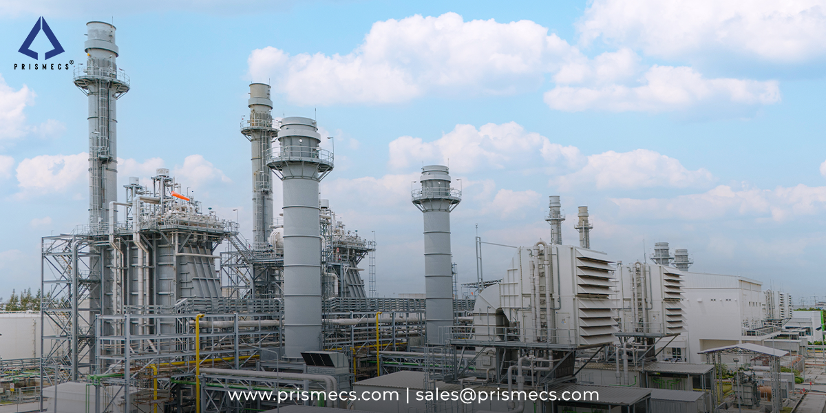
Gas Turbines
19 minutes read
Dual-Fuel Gas Turbines: How Gas-and-Liquid Fuel Flexibility Works
A dual-fuel gas turbine switches from natural gas to diesel at load, but most failures start in idle oil lines. Get transfer steps and coking fixes be...
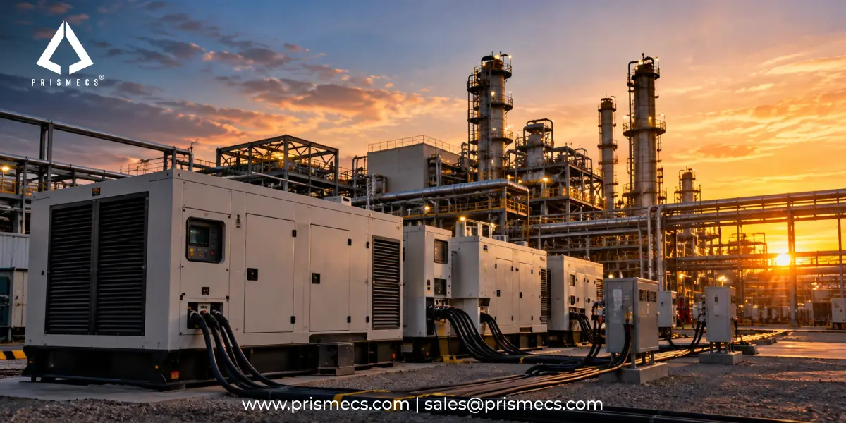
Power Utilities
18 minutes read
Temporary and Bridge Power for Industrial Facilities: When and How to Use It
Planning bridge power past 12 months? Under EPA rules your generators may be stationary from day one. Check Tier 4, NSPS KKKKa and SPCC triggers befor...
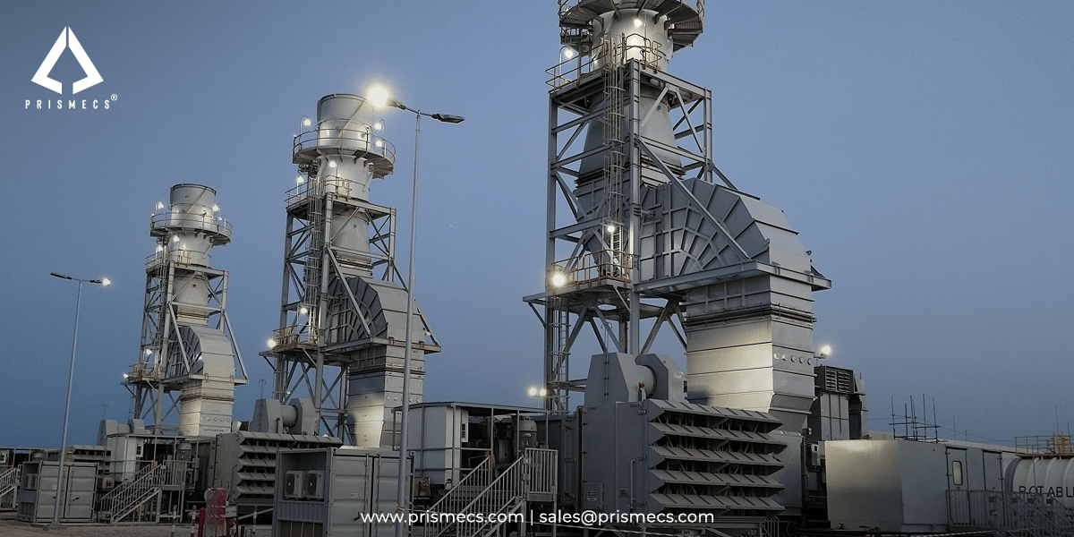
Gas Turbines
16 minutes read
What Is a Mobile Gas Turbine Power Plant? TM2500-Class Units Explained
A mobile gas turbine power plant is a transportable power generation system designed to add electrical capacity faster than a conventional permanent p...

Power Utilities
20 minutes read
Fast-Track Power Plants Deployment: How to Reach Speed to Power in Under 12 Months
Fast-track power plant deployment can hit first power in weeks. See real TM2500 timelines from permitting to COD, proven in Oman and Taiwan. Plan your...